The Coit Tower House
San Francisco finally has a “Coit Tower House” – it only took 86 years…
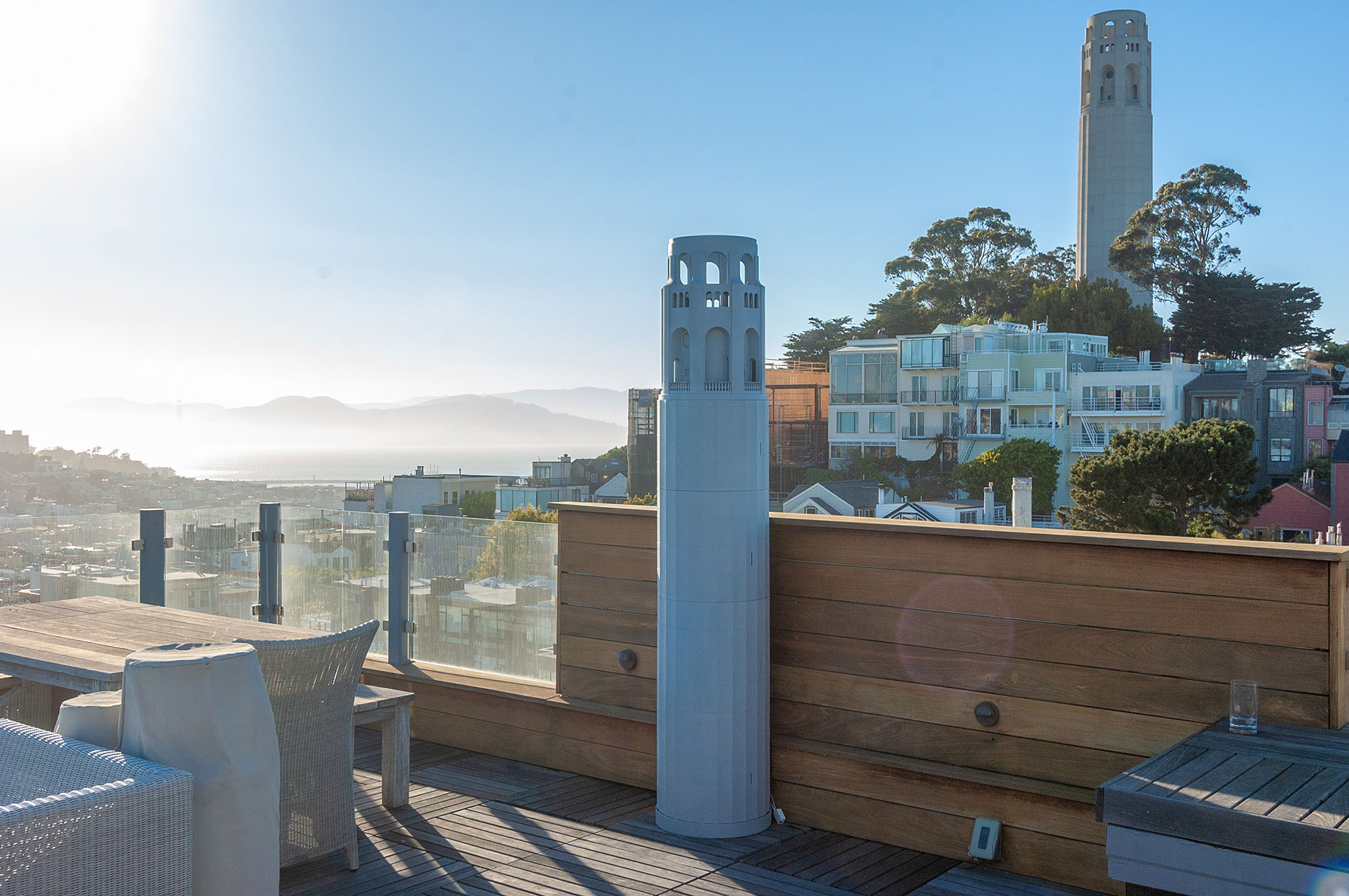
Perhaps one of the more unique projects I've undertaken in the past little while. A great opportunity to leave a lasting mark on the best city in the world – and its art community.
When Paul brought the idea to me after seeing my 1:87 scale Coit Tower I was both puzzled and excited at the same time – a 7'+ tall 3D printed Coit Tower?!
I've been 3D printing since 2013, but I never got a chance to work with a large format printer. It so happened that Creality released their largest printer yet – the CR10S5, and so after a little nightmare of trying to work on this project with a 3rd party 3D printing service, I gave up and decided to do all the work myself. When you need something done right, you just have to do it yourself, as the saying goes. And I have certainly underestimated the amount of time a project like this would take…
Main tower creation process
The base: Month 1
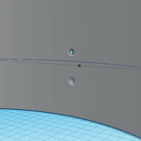
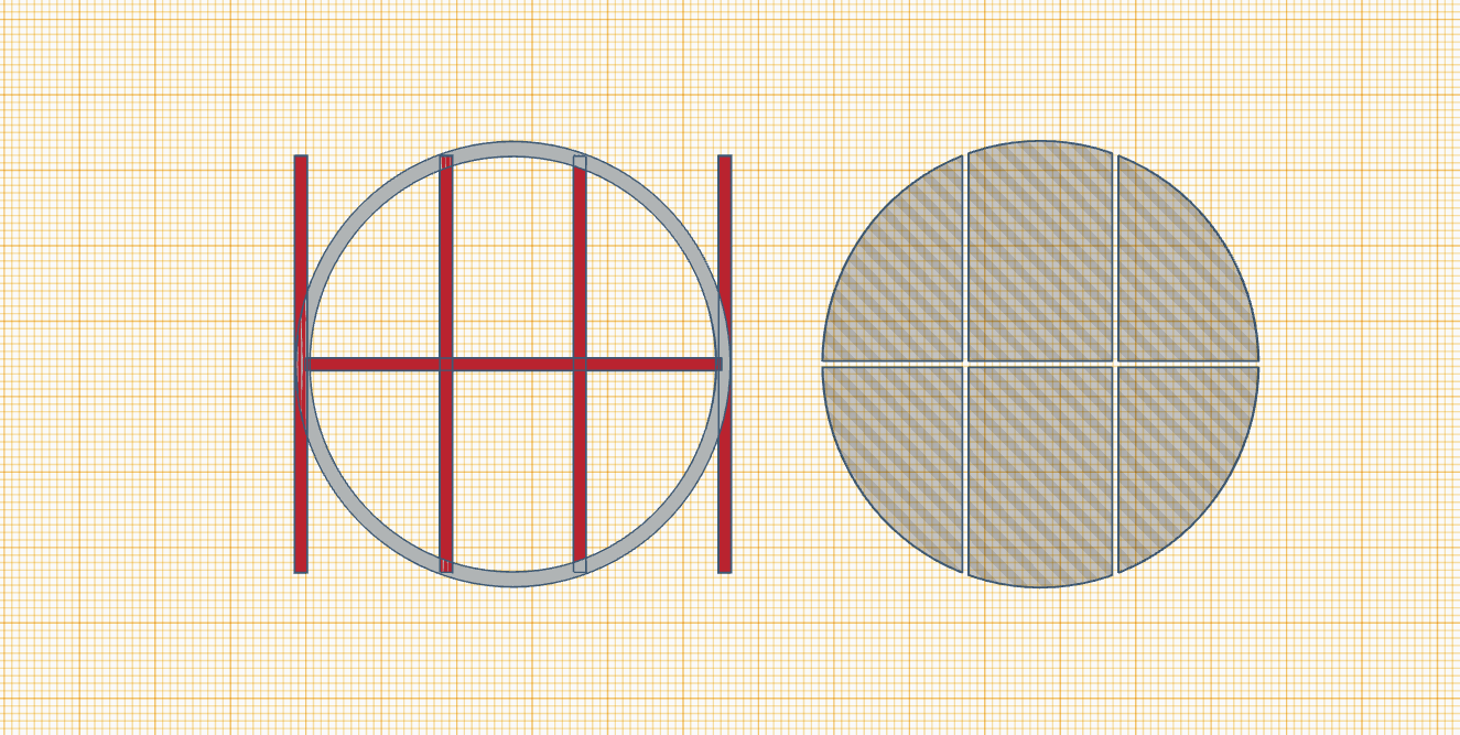
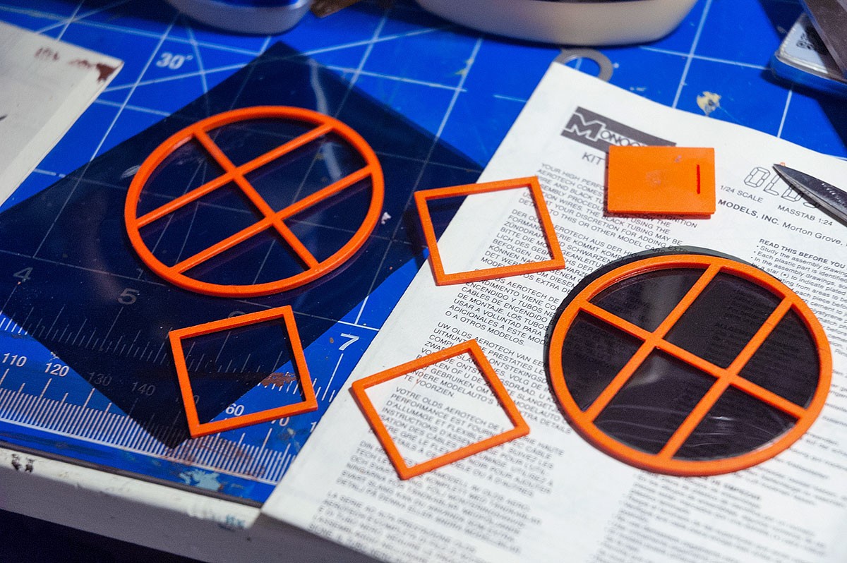
I wanted to avoid using any type of glue in this project, or at least minimal amounts – for such details as window frames, etc. As a result, I had to think up a lot of 'hidden' ways of joining major sections of the tower together.
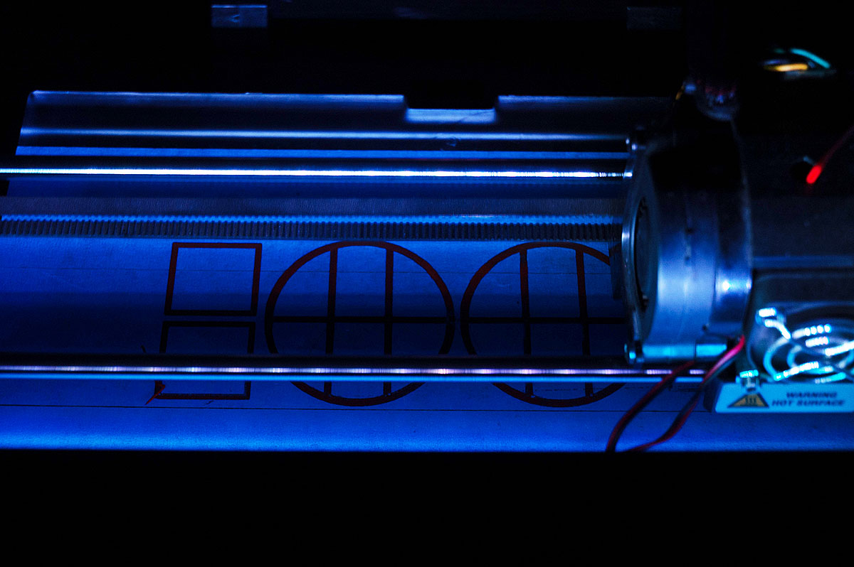
Seen above is the cutaway of the first section (from bottom) and the base ring. This served as a working prototype of the coupling system, printed on Replicator 2. …The only thing that worked from the first try.
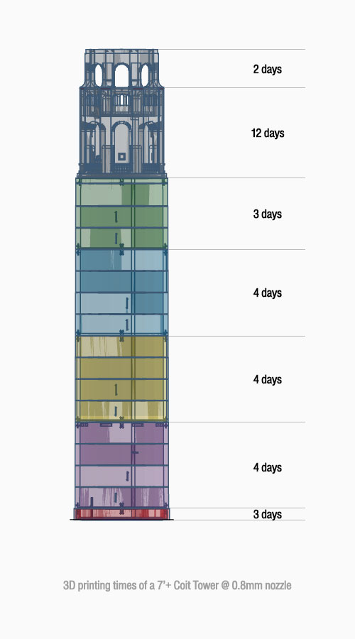
Things got off to a rocky start as soon as I saw the print times using 0.4mm nozzle. This one was replaced with a 0.8mm right away, so the times you see here (in days) are already with .8mm nozzle… 32+ days of just straight printing.
Let's just say that I'm glad I didn't have to build this manually, by hand.
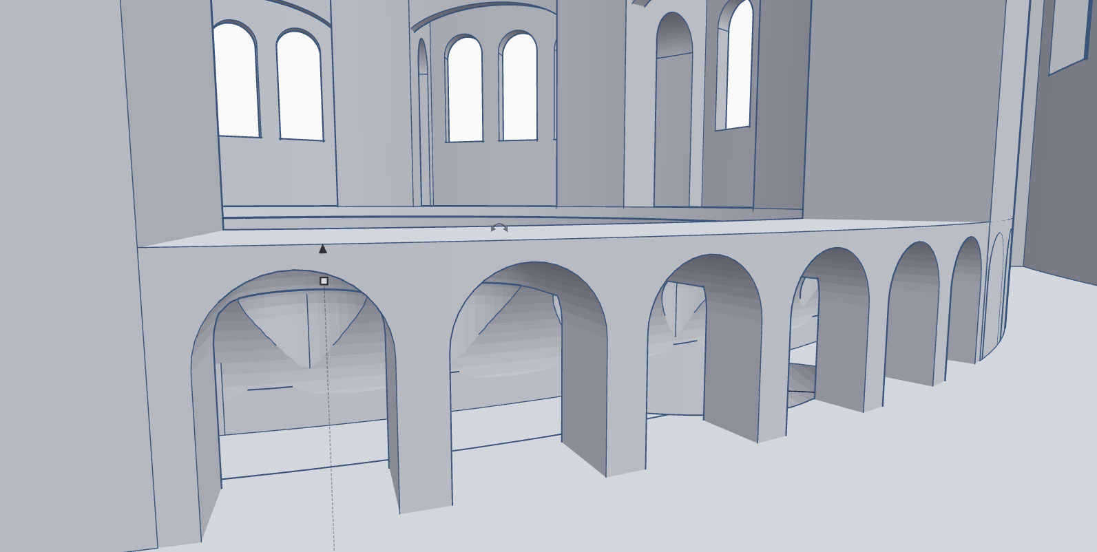
The upscale model is based on my smaller HO scale tower, which unfortunately wasn't high enough resolution for such a large size (7'+). It had to be completely redesigned.
This gave me a chance to really go wild on detail and bring it as close as possible to the real one. In the process I've included a few bonuses – more on that later in the article.
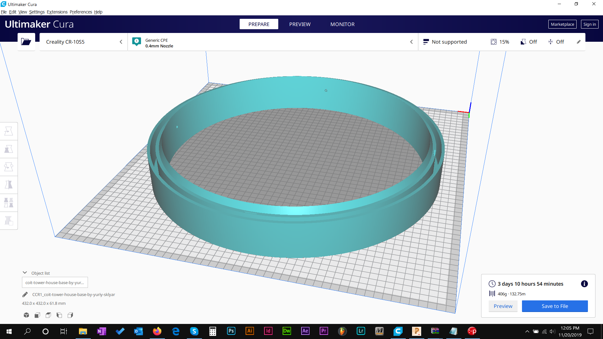
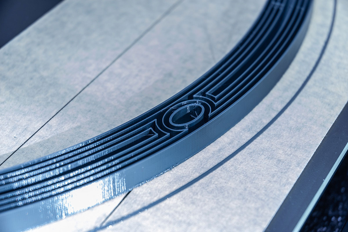
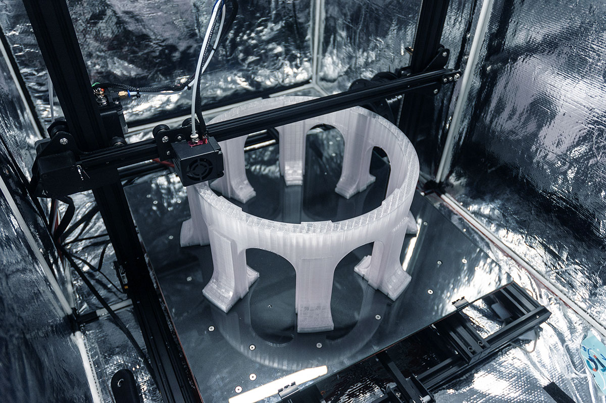
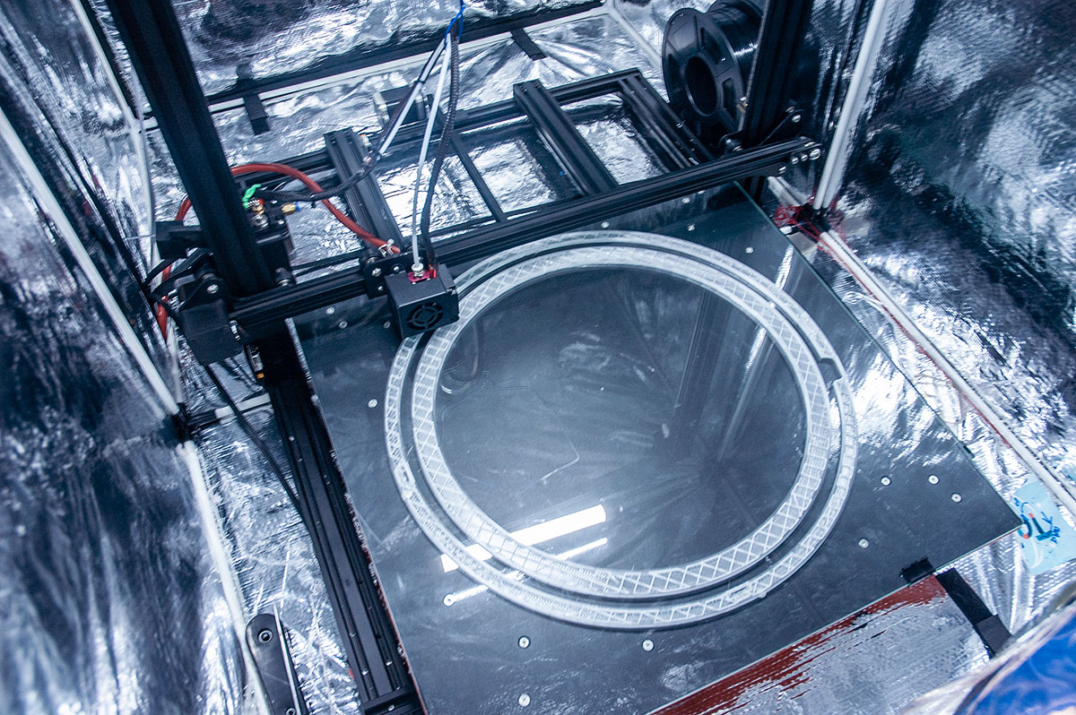
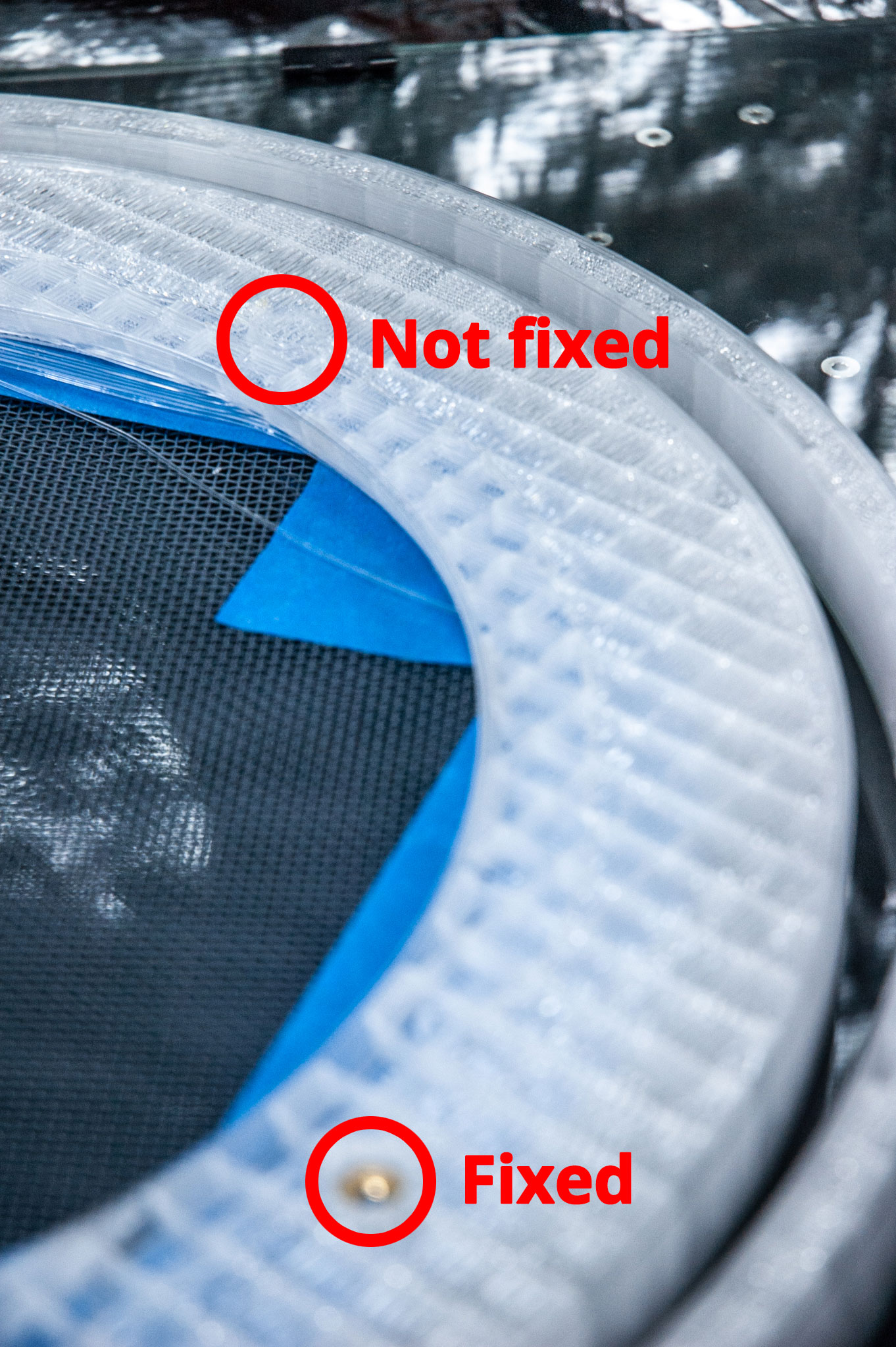
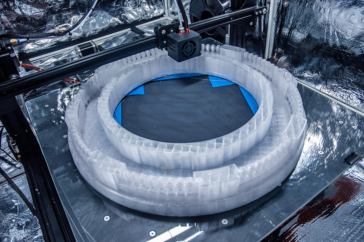
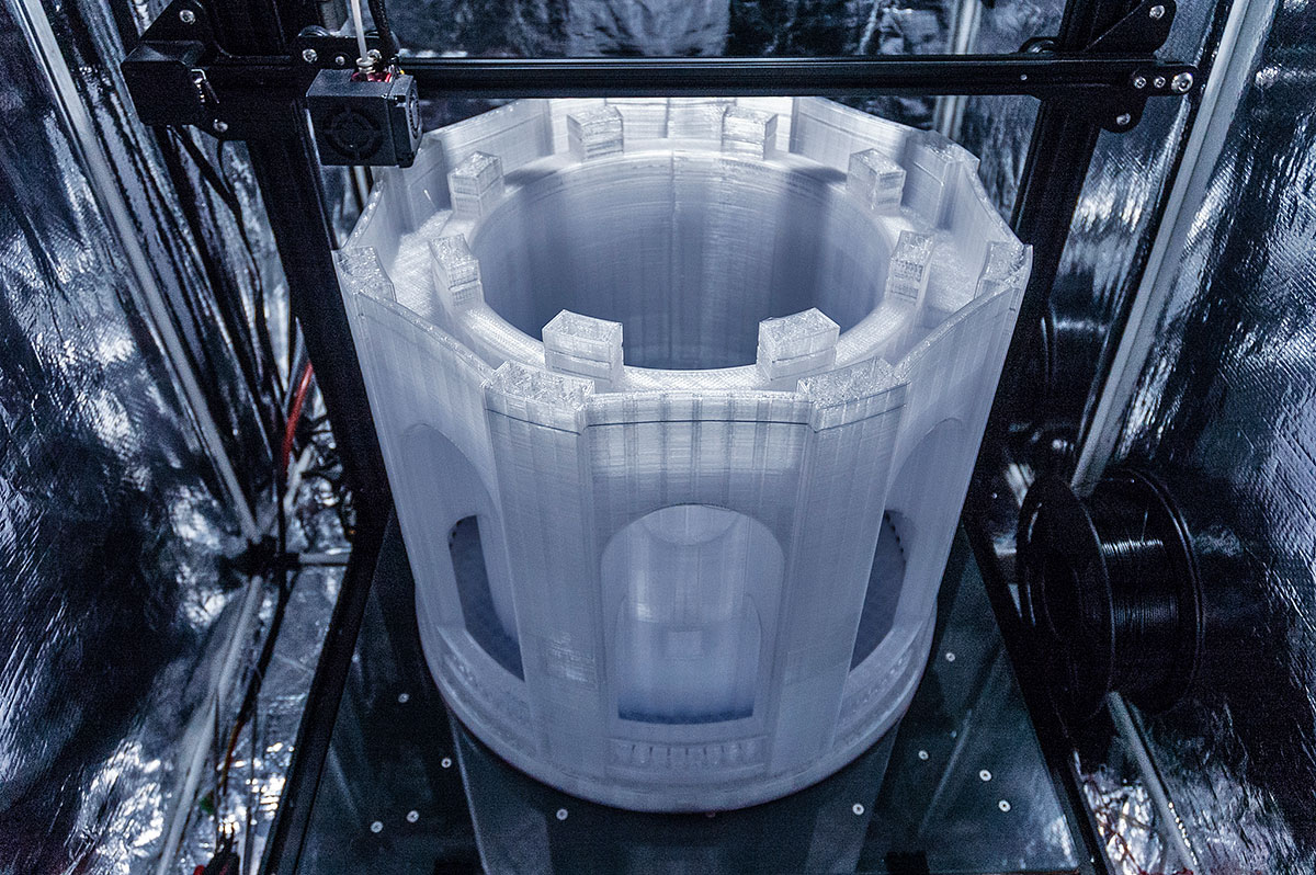
Just as the real tower itself, I started the build process from the base ring. I had to consider the final weight of the tower, which is ~25kg, and design with that in mind. I used 2 shells @ 1.1mm wall @ 0.5mm layer height for the base ring, since the entire weight of the tower will be resting on it for many years to come, it had to be made strong.
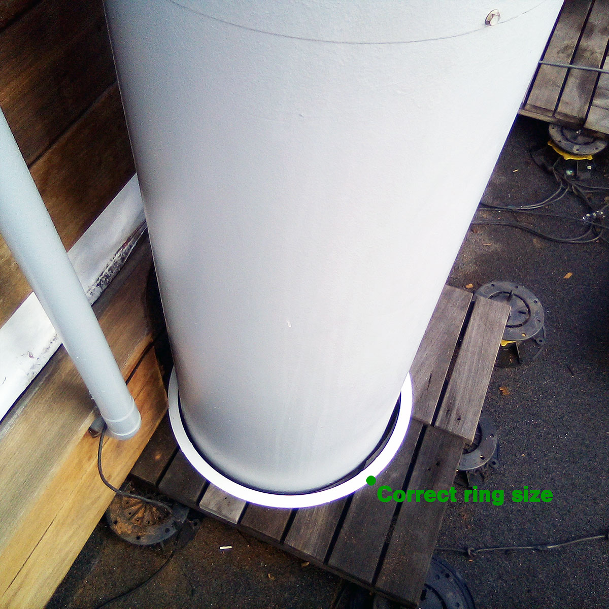
This ring includes a hidden channel for the LED light strip that will illuminate the tower from below.
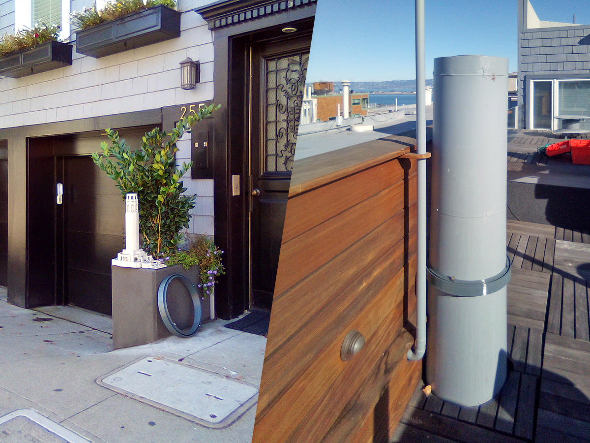
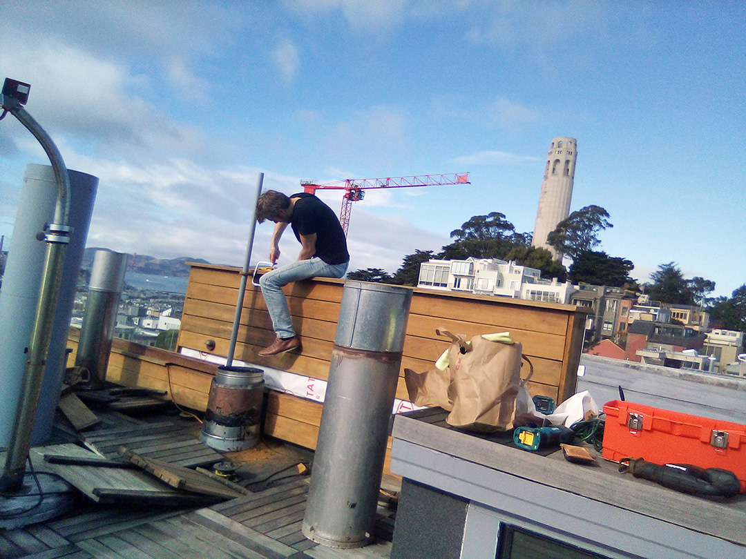
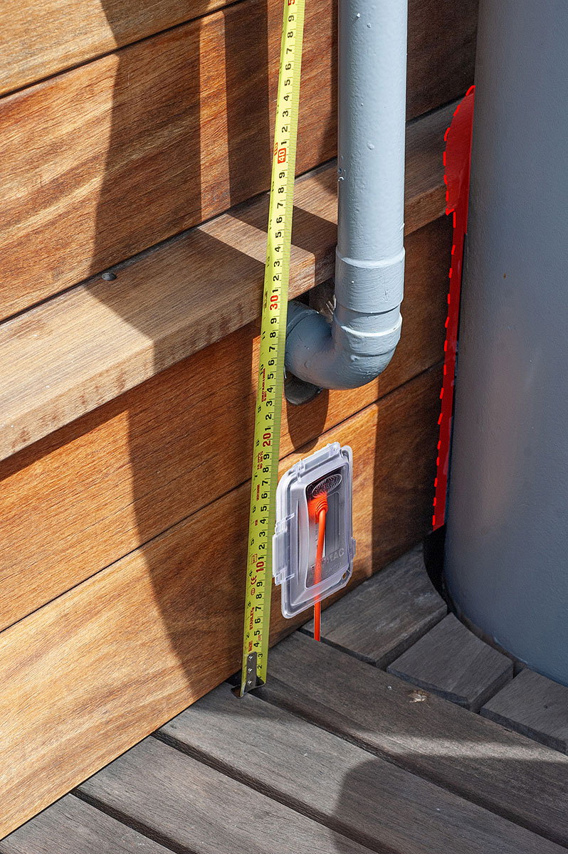
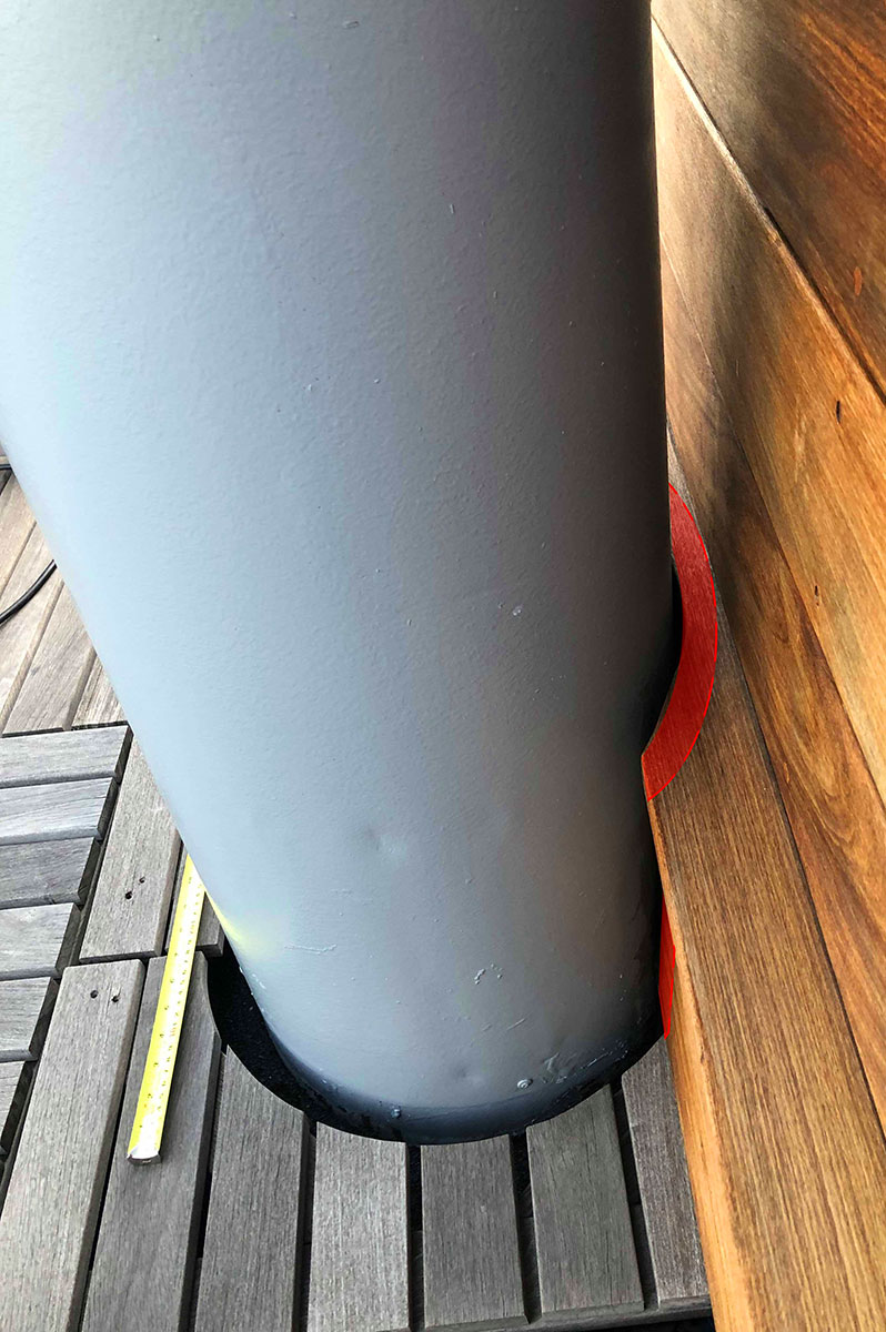
…Good thing I decided to test the initial ring design before printing the rest of the tower. (Because it didn't fit.) Furthermore, in order for us to fit the tower overtop of the pipe, Paul and I had to do quite a bit of woodworking and install a custom power outlet to power tower's hidden lighting system.
What was supposed to be a simple 3-day print, turned into a month long job. This was the first major print on my newly acquired CR10S5, so the first month was essentially spent on printing and re-printing the base ring due to either problems with the printer, or errors in measurements. I must have redone it 5 times…
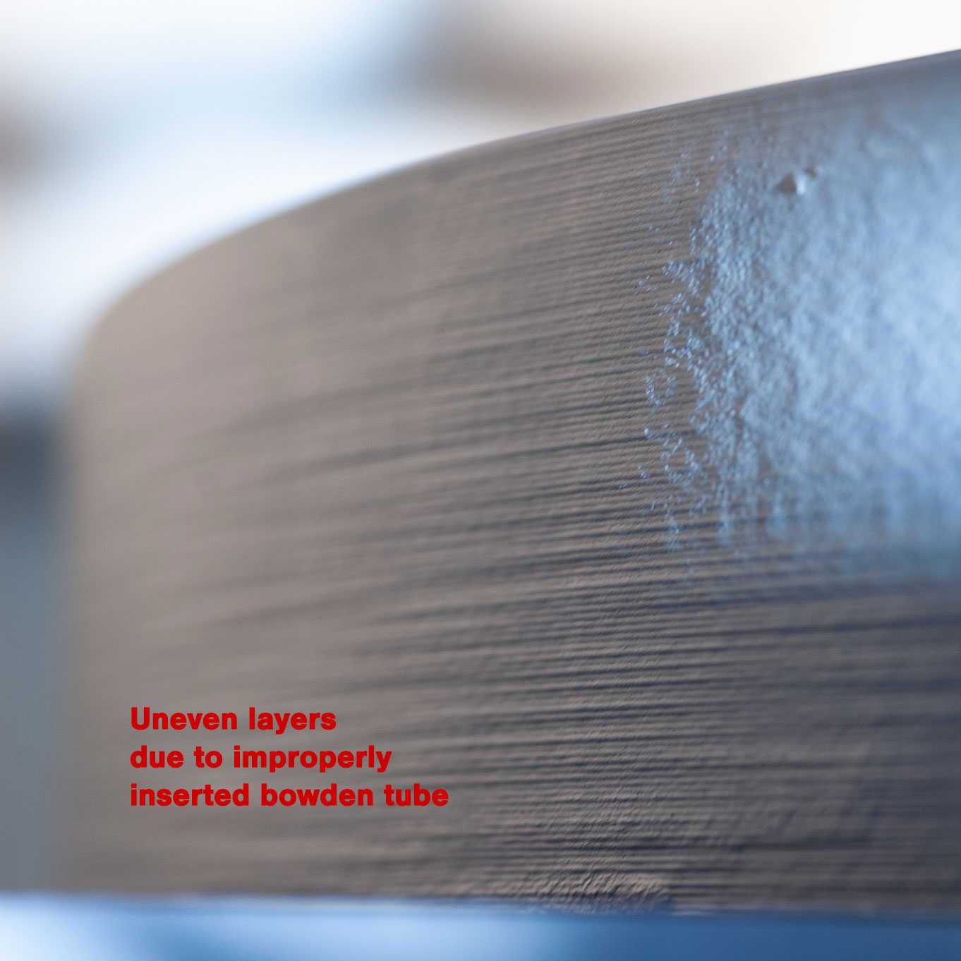
After double-checking that we're indeed working with correct dimensions, I have managed to come up with the below print.
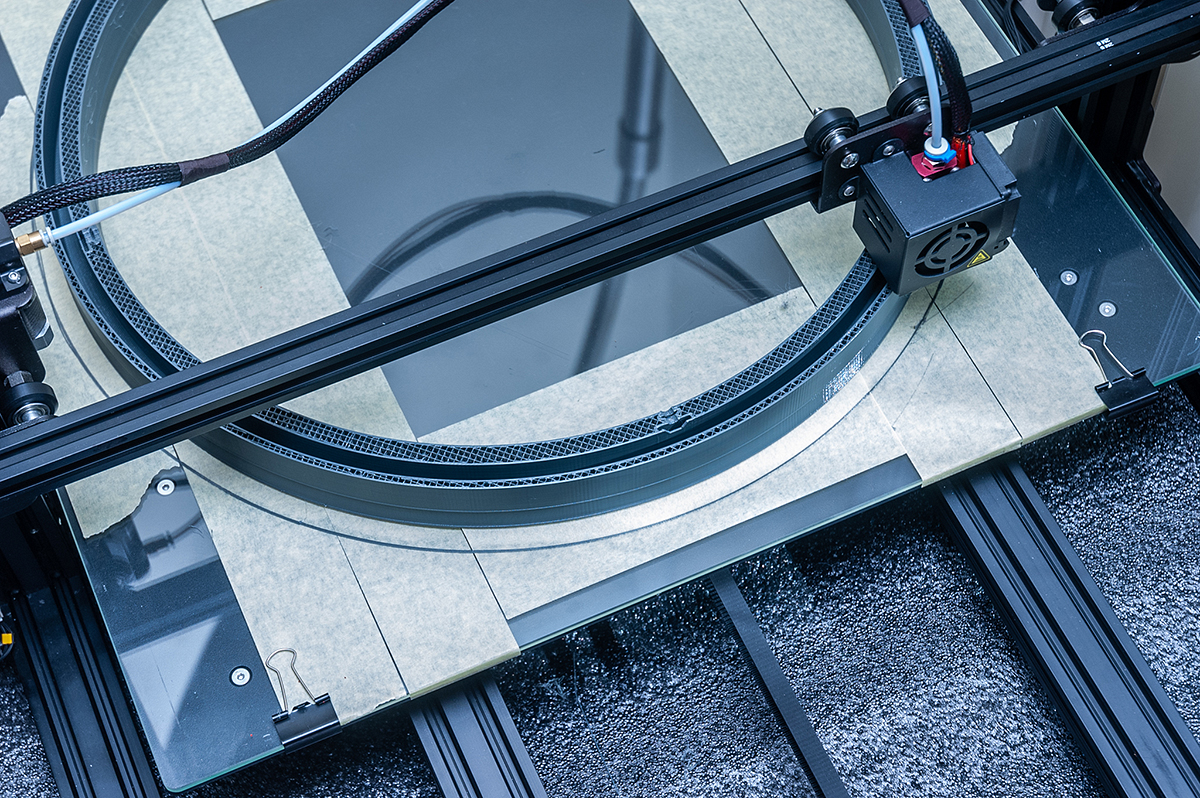
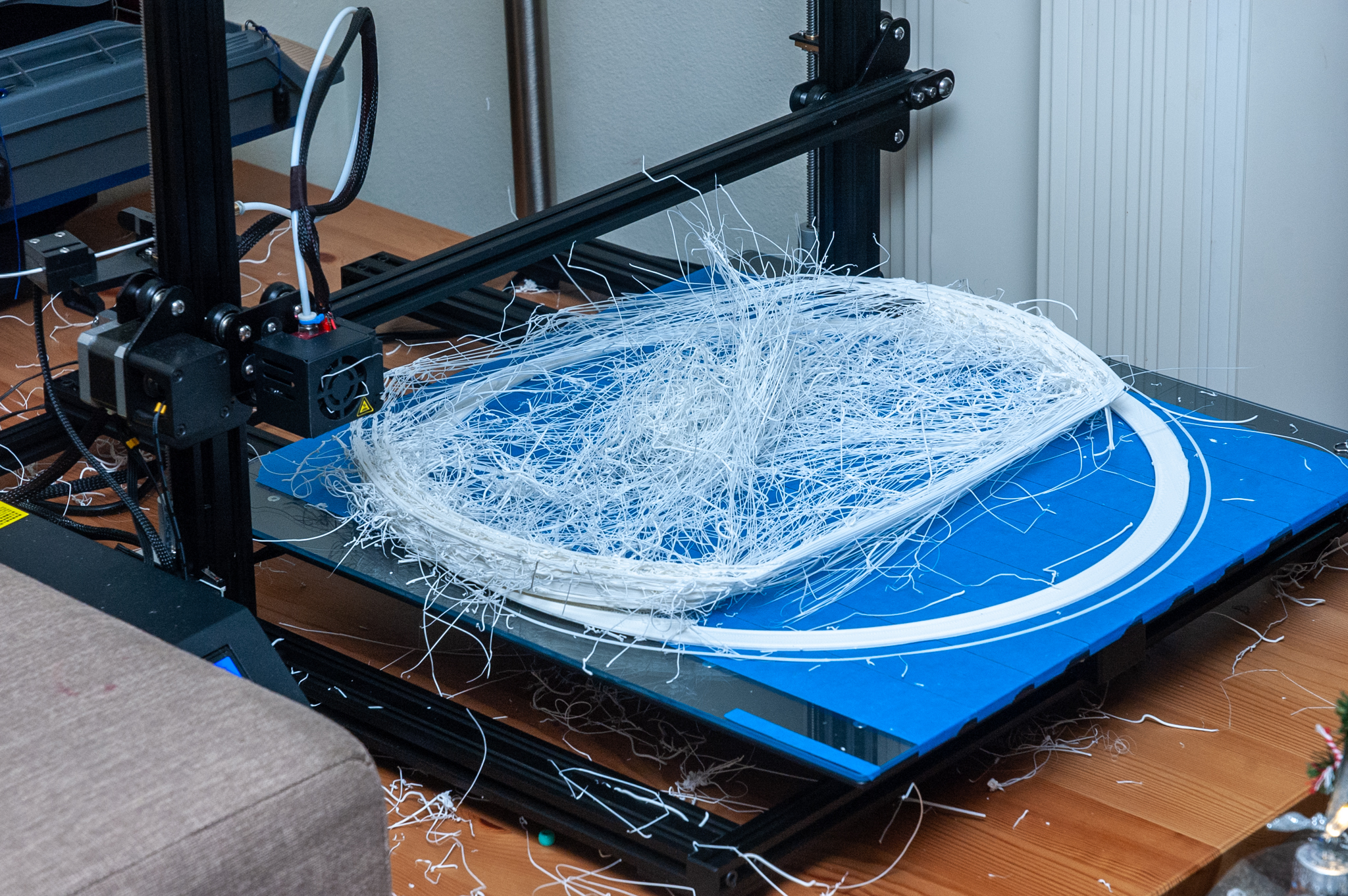
Horrible… Strong, but horrible. This was my first lesson in bowden tubes, and proper, snug fit at the hot-end.
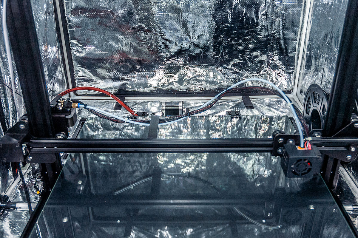
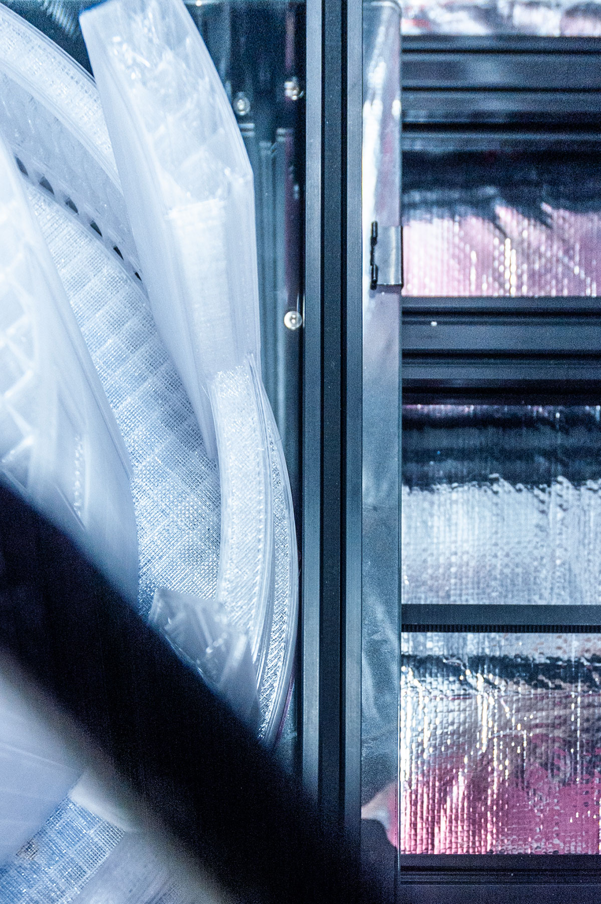
At the time, this came to me as a huge surprise since the initial ring came out near flawless. Near – because it did warp at the outer most edge (around perimeter). Warping was eventually eliminated from all the future prints by getting a heated silicone bed upgrade and a heat enclosure, as I knew there was no printing this project without a large enclosure to keep the heat in. The best purchase I did for this 3D printer.
Month 2
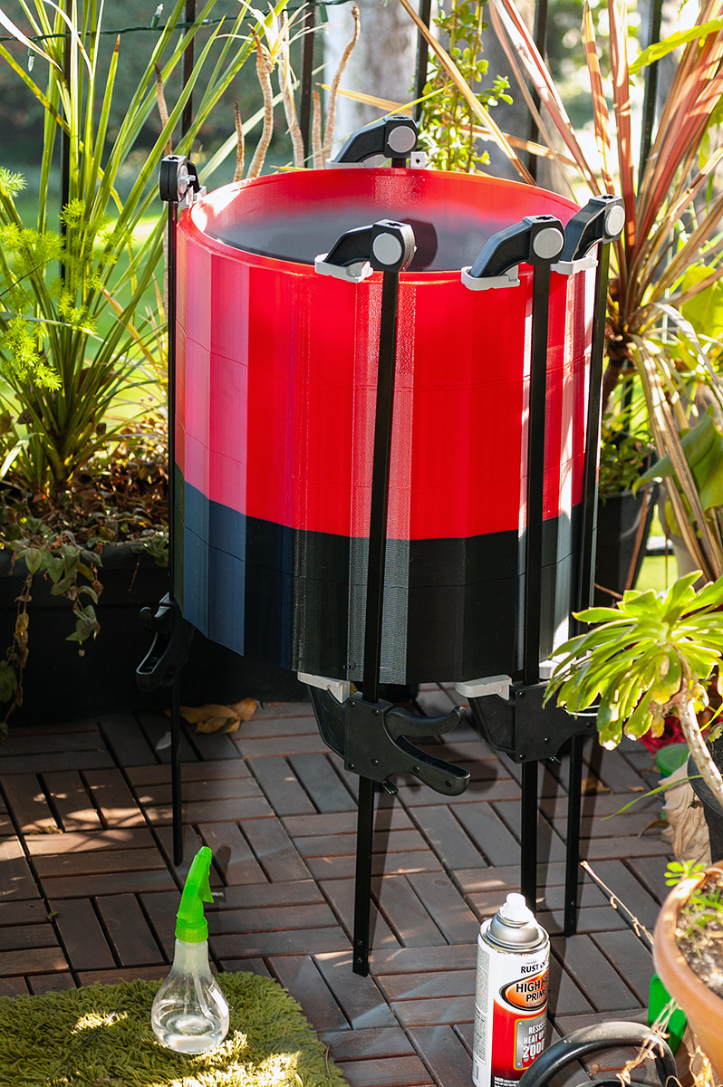
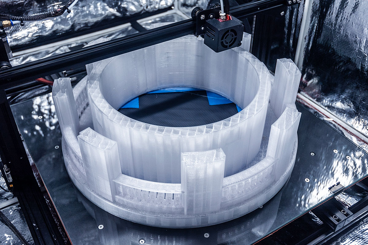
Once I had the printer dialed, I moved on to the next phase of the project – the 4 giant sections of the fluted tower design.
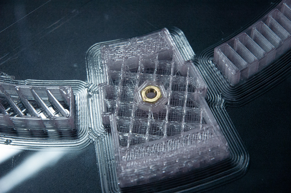
Each one of these four sections, just like the real tower, consists of 4 sub-sections – I wanted to be very accurate with such details. At first these were limited in height by the 3rd party 3D printer, so only 2 sub-sections were supposed to be printed at a time, and then joined together with metal plates and nuts/bolts, but since I was now working on my own terms, I decided to reduce the amount of work for myself, and at the same time reduce the number of bolts/nuts/plates to just 4 sets, instead of 8.
Each one of these sections takes about 3.5-4 days to print using a single 1.1mm shell @ 10% infill, which created for a surprisingly strong structure, since I instructed the infill to have a 45% overlap with inner and outer walls.
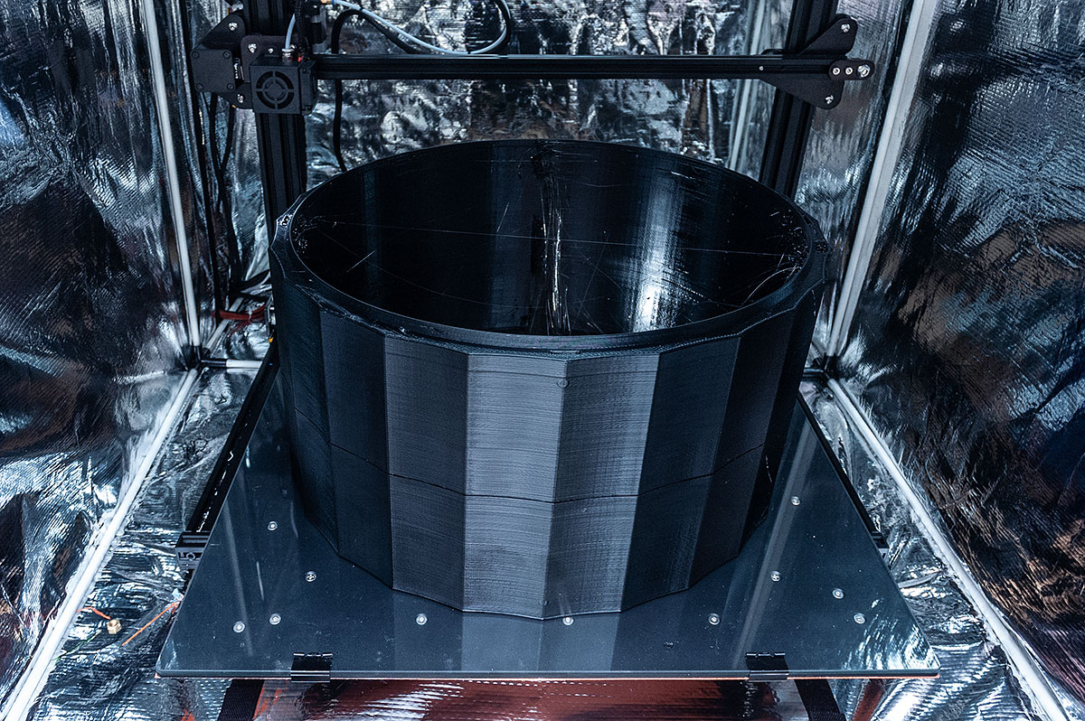
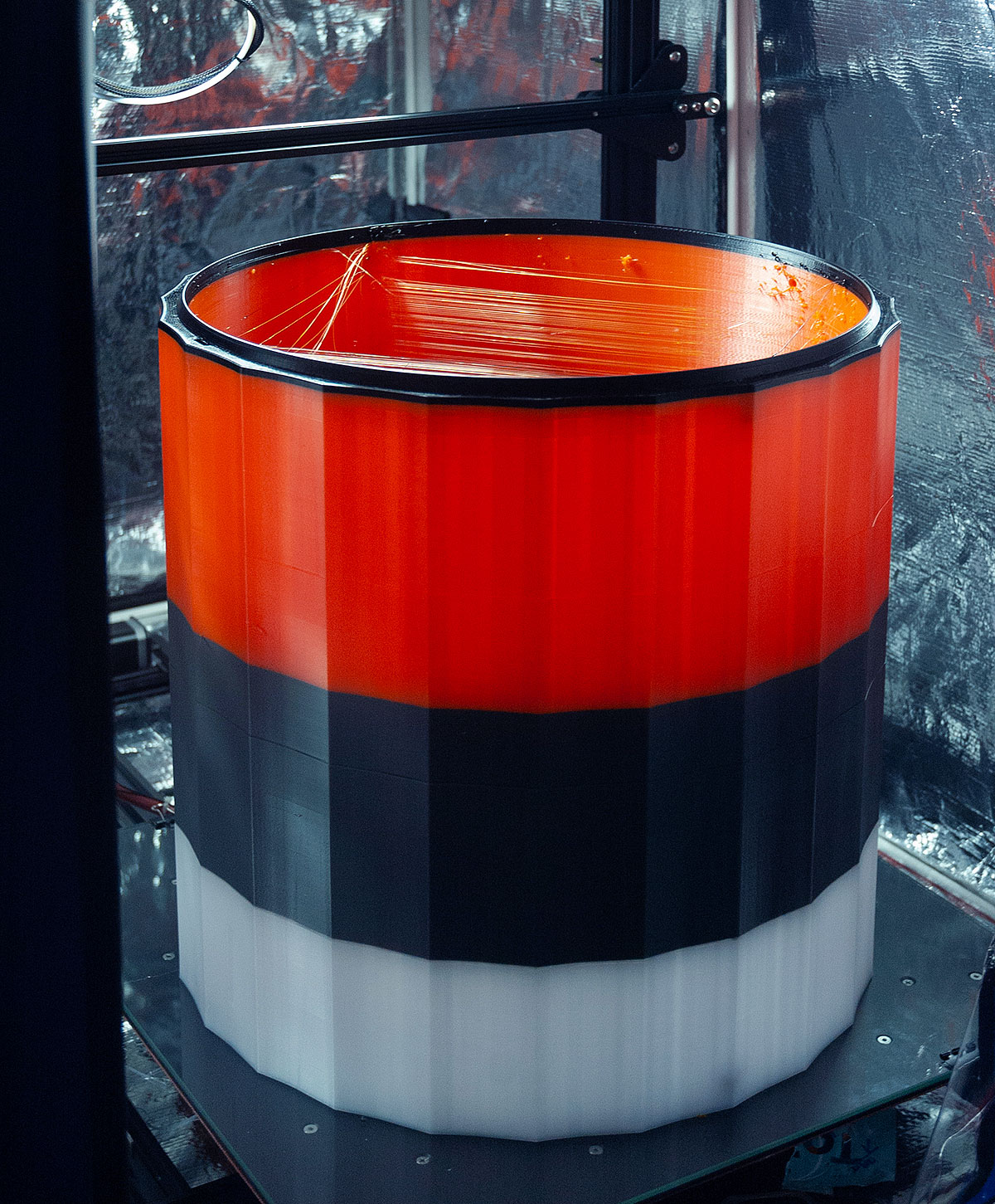
As I was printing each one of these four sections, I took this opportunity to dial in my retraction settings since I was getting a lot of stringing.
The below print of the 3rd section was my first successful print that didn't fail. First one had to be glued out of 3 separate prints, second one out of 2 separate prints. Re-printing these would be too time and material consuming.
Towards the end of the print job, I started ordering single, large 5kg spools as opposed to five 1kg spools. This saved a lot of time of changing filament and reduced the number of failed prints.
Crown creation process
The crown arcade: Day 1
Coit Tower crown consists of three main sections: the arcade, main crown body, and filter. There are two reasons for the making crown arcade section detachable:
- Crown is too big for the S5 print volume.
- Birds. Yes, the ones who can try and call this monument their home by building a nest in the crown. I didn't want to cover up arches of the arcade with any type of mesh to prevent birds from getting in. However, if this will ever become an issue, to avoid re-printing the entire crown to include some type of mesh structure, all you have to do is integrate the mesh into the new arcade design, and simply swap the older open design with the new one.
Embedded brass hardware means the metal won't corrode the tower from inside. Arcade installs using 8 hidden bolts.
Day 2
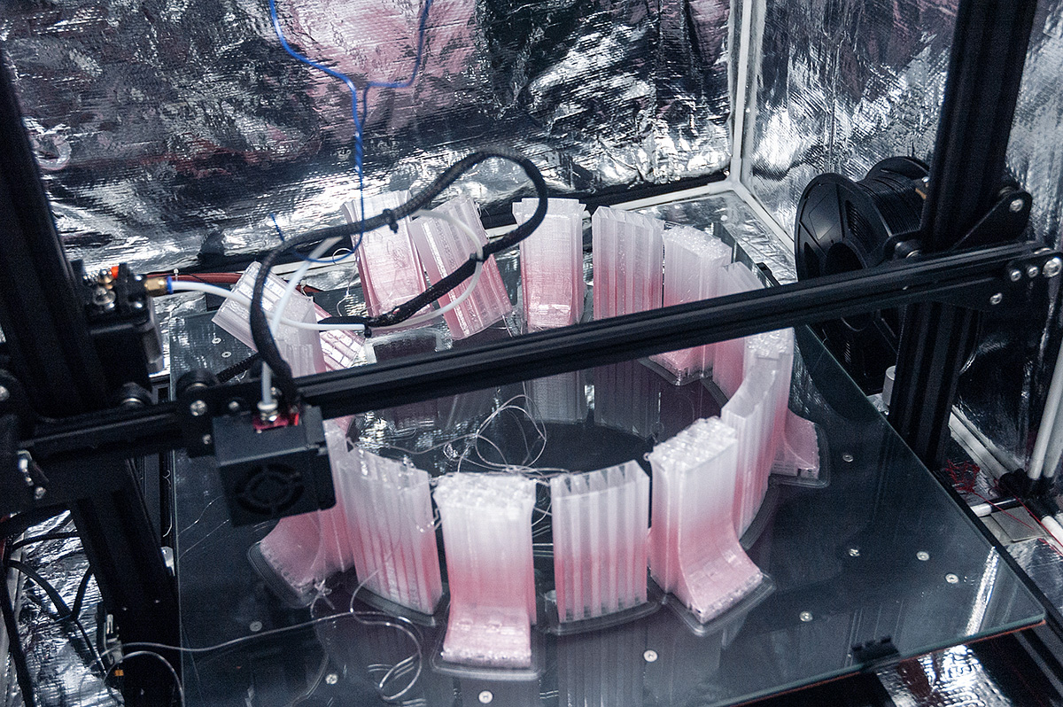
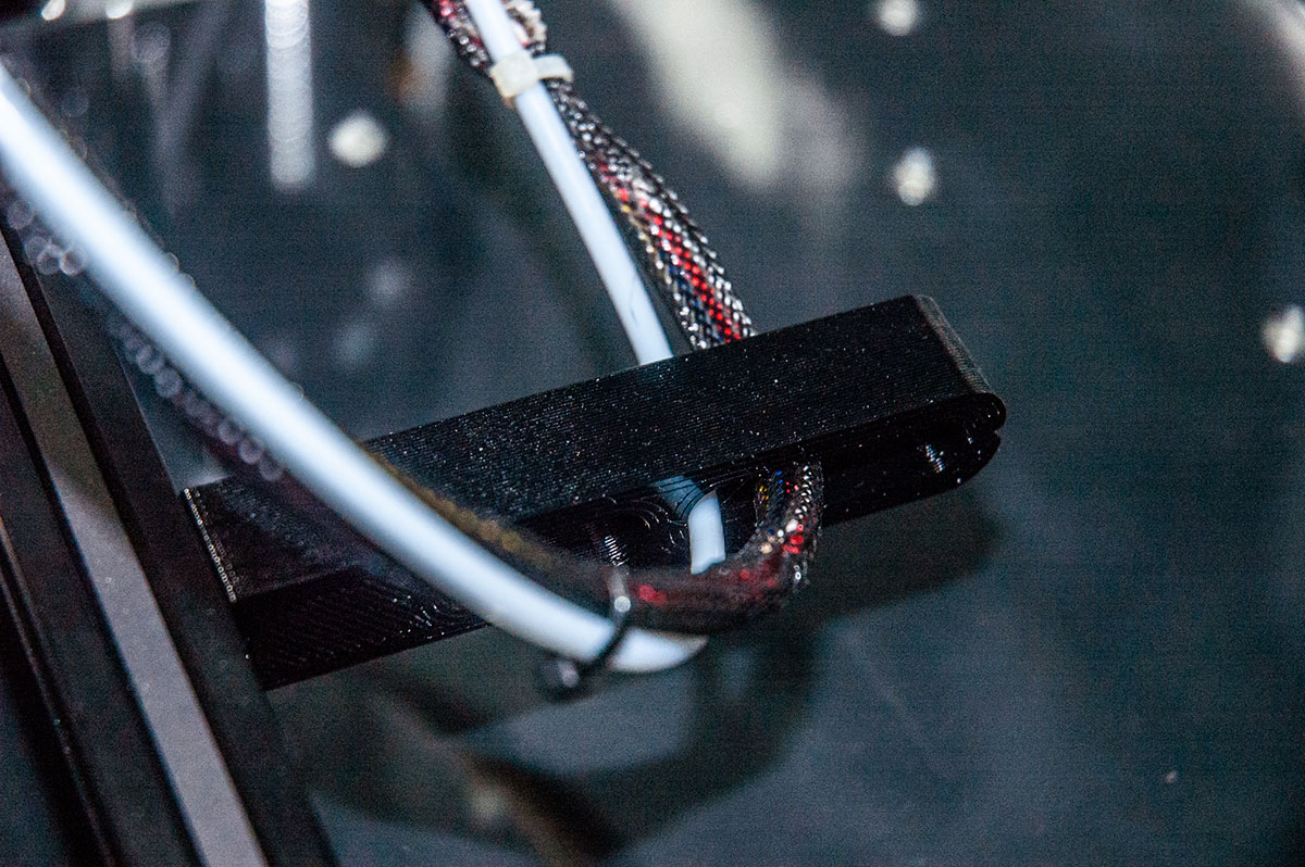
Woke up to this madness. Harness and bowden tube ended up dragging down several columns. To prevent this from happening again, I designed and printed a bowden tube harness bracket holder.
Also, for some reason previous failed print ended up turning pink, even though there were no changes in print settings. Weird.
Days 3-5
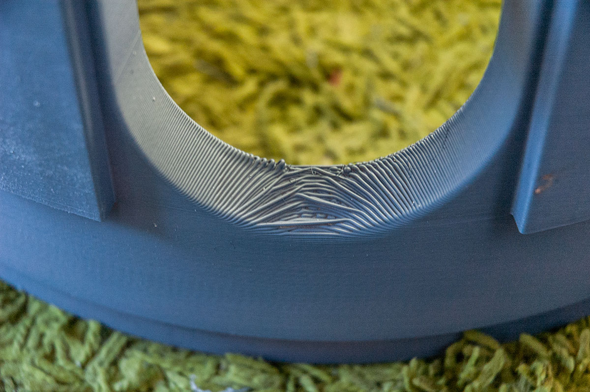
Re: overhangs. Considering that this was printed @ 0.5mm layer height, the overhang sagging isn't too bad, and will be remedied in post-production. Printing this arcade gave me a good idea of just how huge the crown will be…
The replaceable filter
There are two main reasons for creating a ‘filter’, and making it detachable:
- The most obvious one is it prevents things from getting into the pipe.
- The less obvious reason has to do with heat dissipation. Since this surface is separate from the main body of the crown, the crown itself is less likely to heat up to the same temperature. In case temperatures get too hot, the crown will stay intact, and only the filter would need to be replaced.
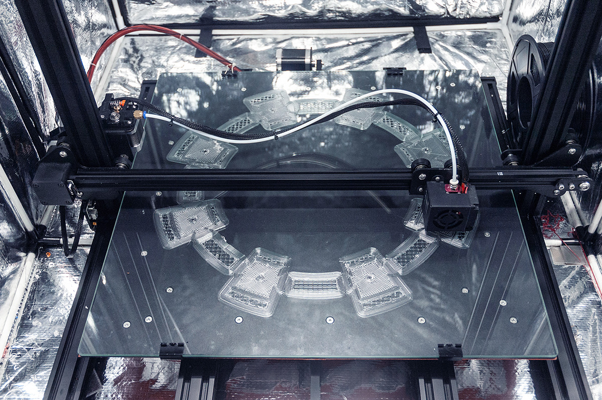
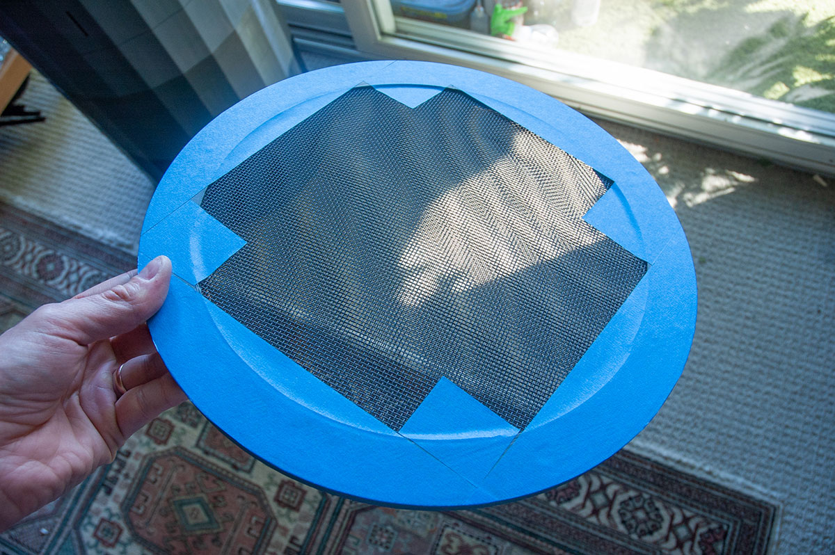
Step 1:
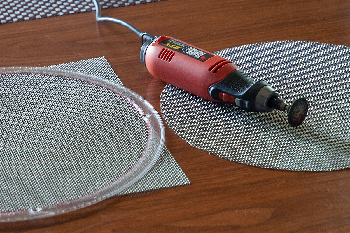
3D printed template for two embedded steel meshes.
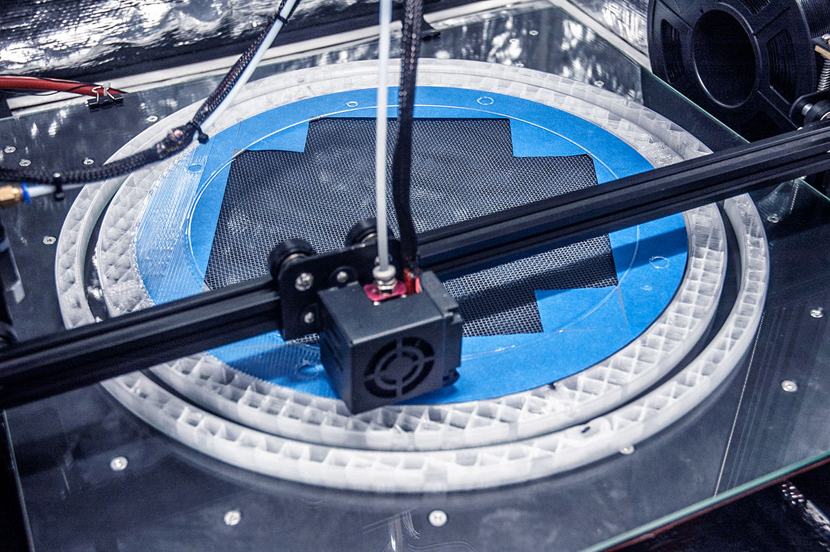
Step 2:
Embed both meshes during the printing process.
Step 3:
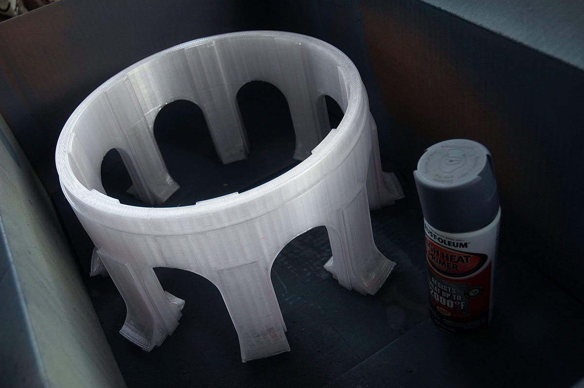
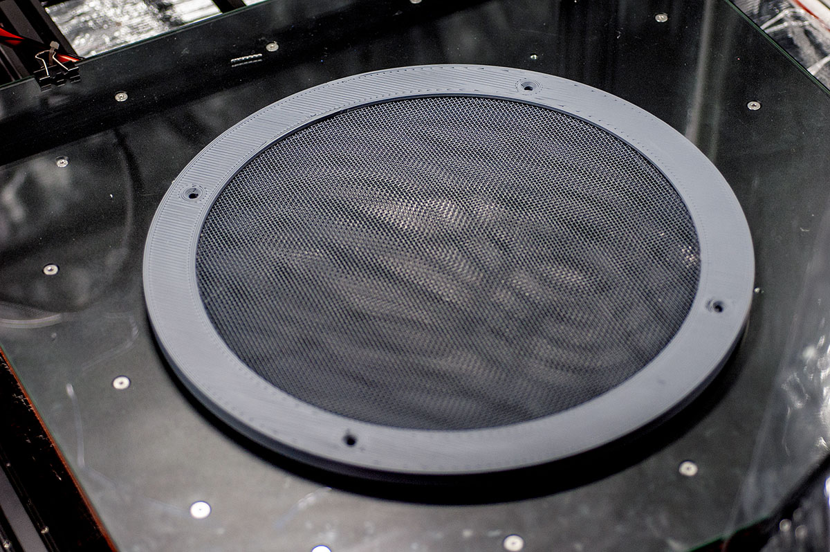
Prepare primed filter for a 9+ day (ended up 12 days) direct contact with 85C bed.
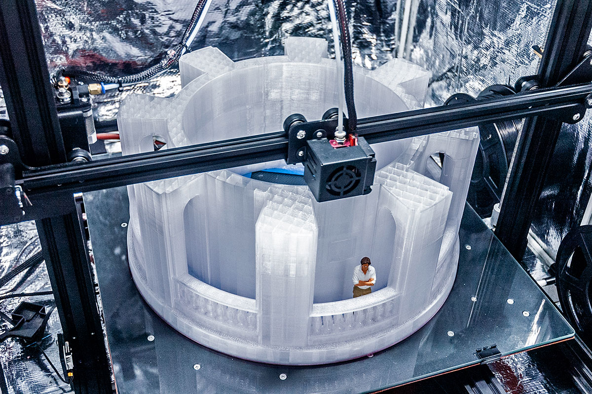
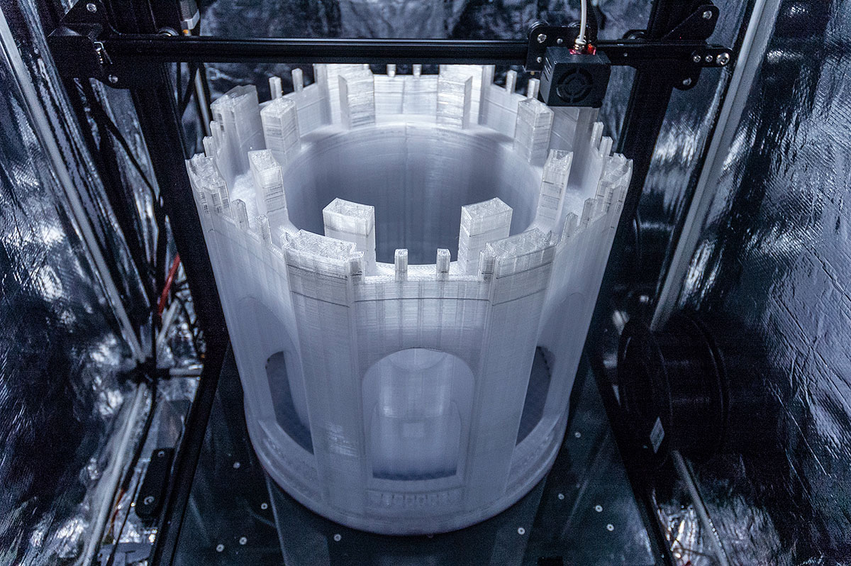
Main crown body: Day 1
Filter in this case also doubled as a support structure. I wasn't quite sure how well it would work out, but I've managed to pull it off with just a few small imperfections.
Day 2
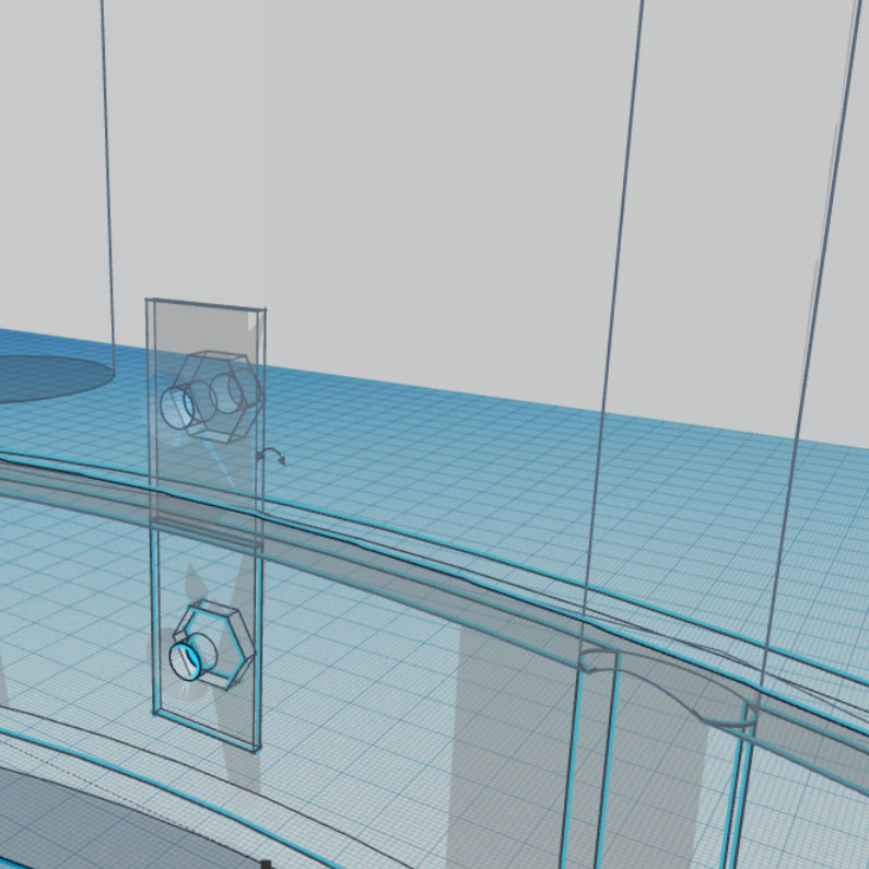
Good thing I got back on my schedule of waking up at 2AM. Woke up to enclosures for nuts that detachable filter uses to screw into completely covered with at least 4 layers of roof.
Had to open up each one of the hexagon holes (for nuts) with an Xacto knife and clippers. Intense process as you must be careful enough not to shift the print/bed. None the less caught it in time for it not to bury them for good.
Seen in below photo: hole at the bottom has been opened up and a nut has been deposited inside, one directly at the top hasn't been opened up yet.
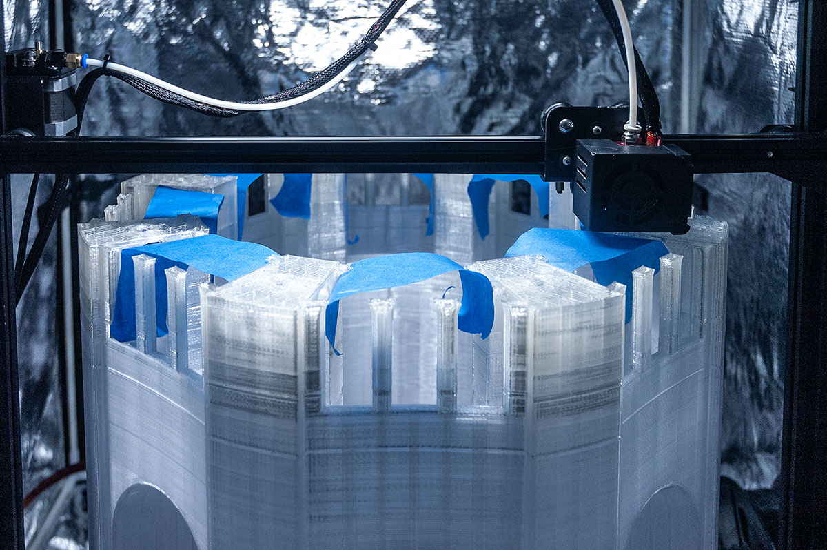
Day 3
One thing to know about this project is that it uses 0 supports (besides in one area of crown arcade, which was unavoidable). I had to design for that. So there are a few "experimental" areas, where I'm ‘gambling’ so to speak. One of these gambles was the railing part as it originates from posts and then overhangs quite a bit.
Day 4
Railing worked out perfectly. (Gives himself a pat on the back after a huge sigh of relief - all the things that could go wrong so far into a print.)
Smaller gambles were window overhands - I will have to touch it up with filler/sanding, but overall it took only 2 layers to perfect it after.
Next big gamble of the day is the doorway. Thinking I might help to manually support it somehow.
Day 5
Print failed 4 days in, and I noticed when it was already several layers in.
So after taking a day off from printing (while up-keeping constant temperature of the heat enclosure/print bed) to really understand how gcode operates, I now have a much better grasp on the subject matter, to a point where I was able to restart the print from where it left off.
In order to restart printing from precisely the same location, it was imperative to home the device. This was the scariest part on a 4 day print job, not going to lie. But some things in life are just meant to be, so it is with millimeters away of the print, that the gantry cleared to successfully auto-home. WHEW!
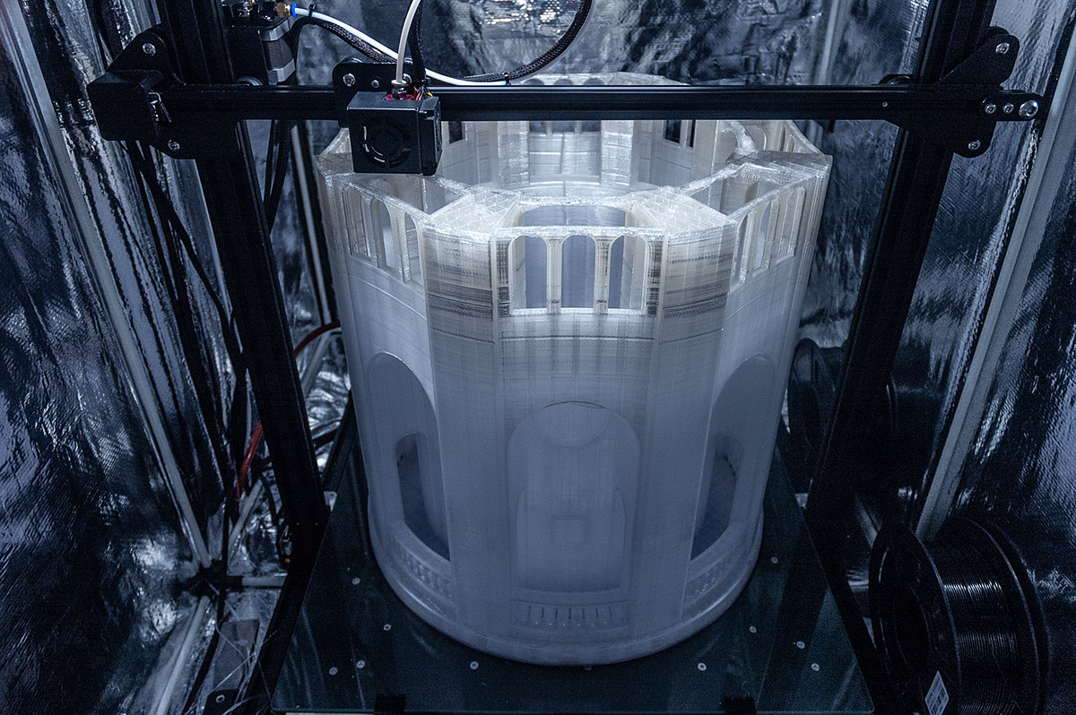
Day 6
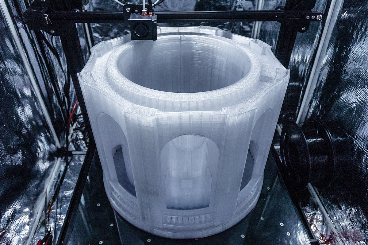
A gamble point for this stage were the overhangs of all 8 arches... These will need some manual fixing after, but definitely better than printing with support...
I am now watching things from up close, too - ensuring nothing else will go down.
Day 7
Smooth sailing before the approaching storm. Woke up to printer starting a second floor layer (out of 4) of the Lantern Level. This must weigh over 6kg at this point.
I wasn't sure about the giant arch overhangs since they by far looked to be the biggest overhanging arch structures of the print, however the way the Coit tower is designed, actually made them much more resilient to sagging - just a layer or two at the top which I will patch up manually.
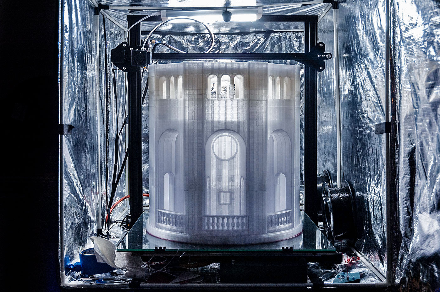
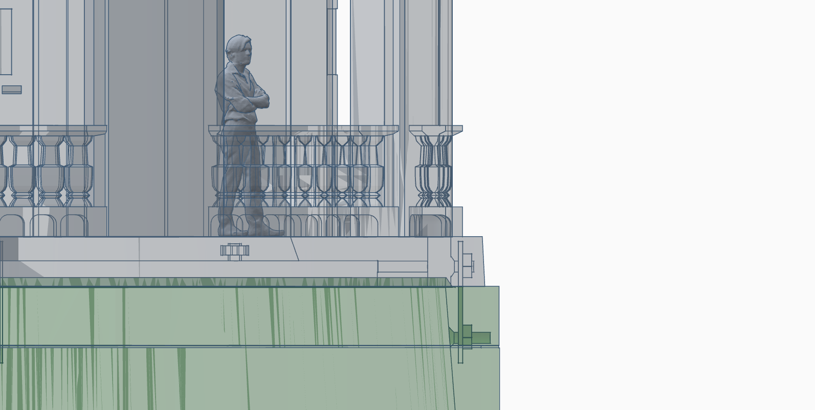
Fun fact: the observatory part of Coit Tower is 55m (180') above the ground. This observatory has two main levels: main being the “Belvedere” (one with the railing), and the observation deck – the “Lantern Level”.
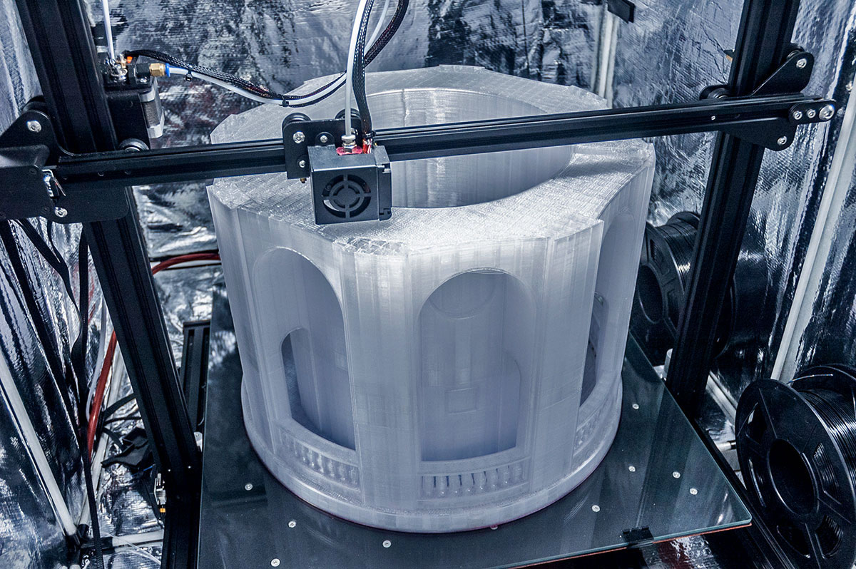
Gamble of Day 7 was a 360 degree light arcade designed to house an LED light strip. Wasn't sure how the printer will behave, but all in all it performed much better than expected!
…In the other end of the room a MakerBot is also working to assist the build.
Last minute I have decided to separate all the window frames to make them more precise and so I could insert plexiglass behind them, which will simulate the window effect (while painting the window part of the tower black). Seen in the 3rd photo is a magnetic light service hatch – more on that later.
Day 8
Spent the entire day troubleshooting clogs. Insane clogs. I checked EVERYTHING, and in the process even updated the plastic feeder to an aluminum one. Later I found that the factory feeder mechanism was snapped due to spring pressure, which would explain the poor feed.
This didn't solve the issue though… In the end it happened to be my Gcode. In particular my insane retraction setting of 12mm @ 55mm/s. However it wasn't the retraction rate itself, but Cura's option of filling all tiny holes. For some of them it was barely even pushing out any filament, so it was quite pointless. Lesson learned the hard way.
Day 9
By now the print should be nearing completion, however that won't be the case… Seen below is my 4th print resume. Thinking I'll be upgrading to a MicroSwiss hot end and Capricorn tube. ...Good thing I learned how to resume. uhhhh
Day 10
After a few more filament jams and some 'last minute supports', I miraculously got it to this point. This proved to be the most challenging part of the print because I sliced it to fill all the gaps. BIG mistake. Some gap fillings were so tiny, that it would just grind the filament to a point where it breaks since it has to retract 12mm each time; repeat it x8 per layer in some cases, and you get the idea…
Day 11-12
After the print failing TWO more times that I didn't catch (there probably were at least 10 times that I did catch it by sitting through/assisting delicate sections of the process), today I have finally FINISHED this beast! What a process it was. Education is priceless though!
Love the cracking sound printer bed and the 3D printed part make upon bed cooling. Comes off by itself.
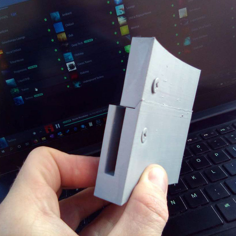
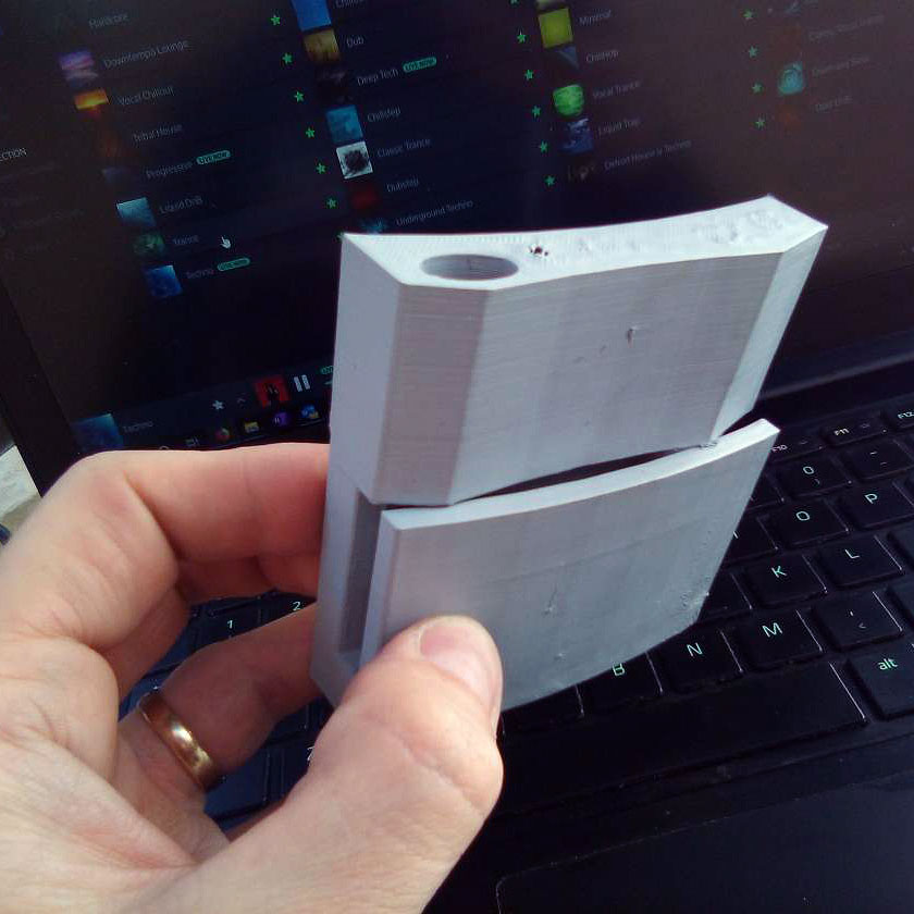
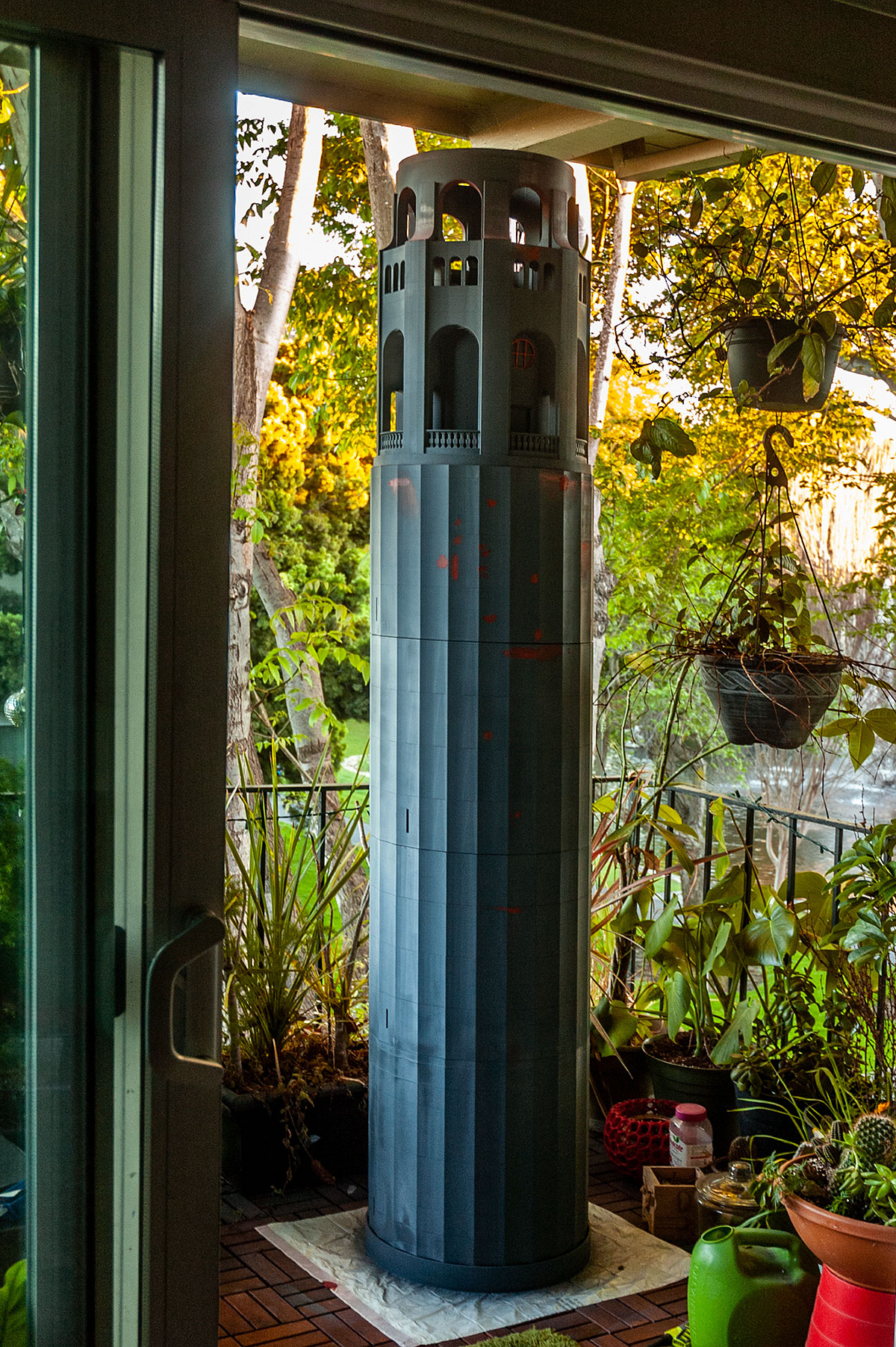
Seen below is how the crown attaches to the rest of the 4 main tower sections.
Assembly & post-processing
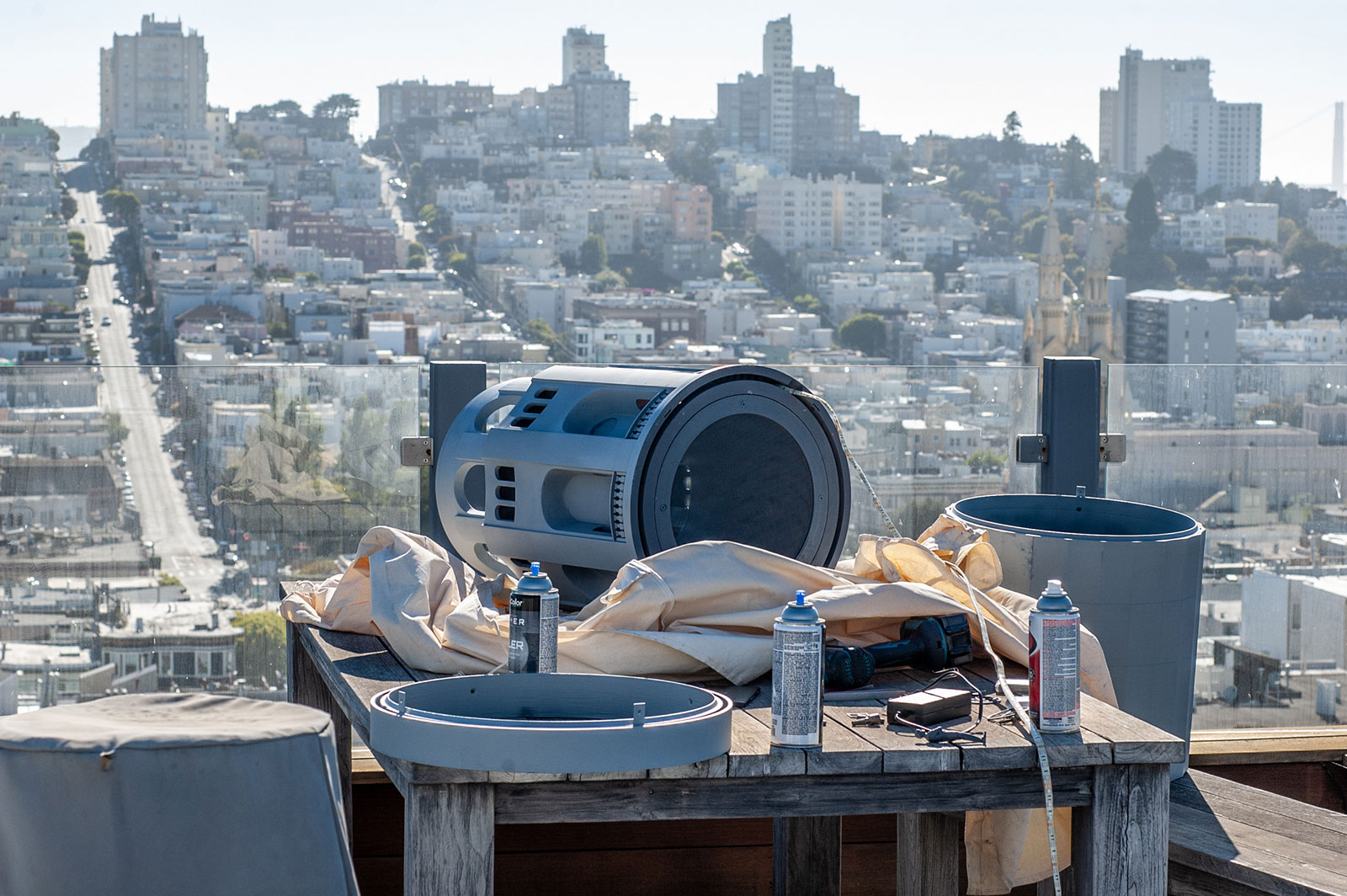
Notes:
- Problem with previous 3D design was that it wasn't high resolution enough for the 7'+ size of the tower, so the entire 3D design had to be redone from scratch, using previous model for proportions.
- Custom Tinkercad shapes had to be created that increased the polygon count on cylinders, creating a smooth, polygon-less surface.
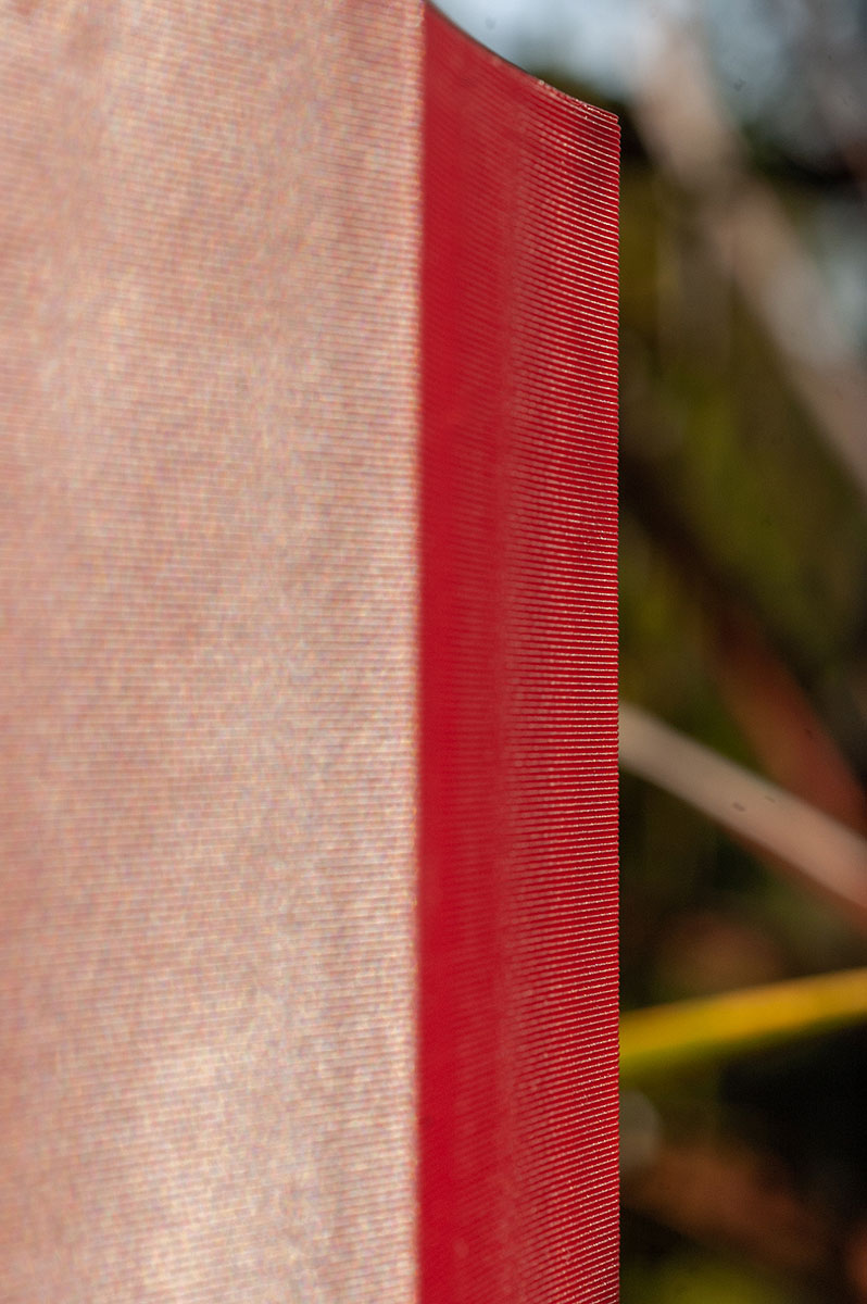
- Printed out of self-extinguishing material with a glass-melting temperature of x2 as much as it could ever get in the hot California sun (85°C).
- Printed using ColorFabb's nGen filament, SUNLU PETG and Gizmo Dorks PETG, which are known for fantastic self-extinguishing properties (this is an exhaust outlet after all).
- Covered with 5 layers of primer which can withstand the heat of up to 2000 degrees Fahrenheit. Refined with Bondo.
- Print and the 3D design themselves max out both the 3D application (Tinkercad) and the CR10S5 in terms of workable volume.
- Approximate scale is 1/20.
- Each tower section takes about 4 days to print – there are 4 of them, not including the crown.
- The crown is a 9-day print and includes embedded hardware, just like each one of the tower sections.
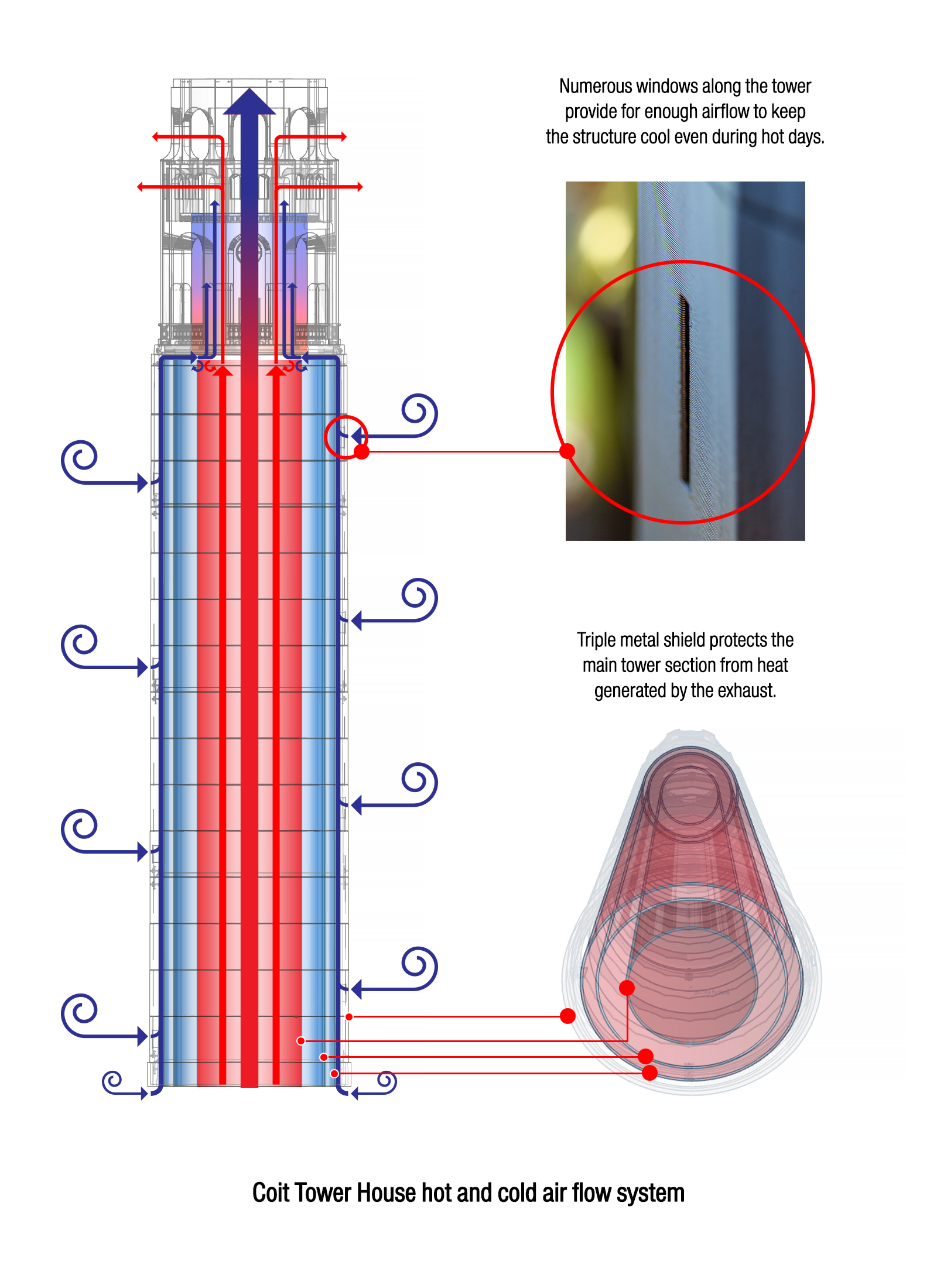
- Many windows throughout the main tower column allow for airflow to keep the tower cool in moments of extreme heat.
- Columns are joined by steel plates that are secured with bolts and in-printed nuts.
- Just like the real one, the tower features a tapered design, meaning that each section is smaller than the next one.
- Big design challenge to overcome was the fact that I didn't want to use glue, so parts had to be designed to be fastened using a hidden nut/bolt system.
- Brass hardware = corrosion resistant.
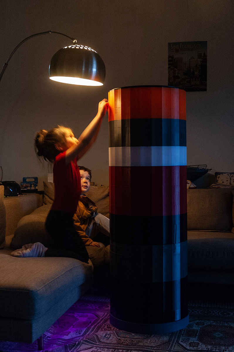
- V2 of the tower includes smart tech that allows it to stay synced to the real-time color of actual Coit Tower.
- 9/28/19 = official start date, though the project has been in the planning since 4/23/19.
- For whatever reason 356 (mm Z) happens to be the magical number at which several prints have failed...
- Total weight = ~24kg (including all the hardware).
- ~7.777km of filament used.
Enjoyed what you saw? Stay updated by following me.